I/O-Modules
Fieldbus Terminals
Lightbus - Coupler

Product Description
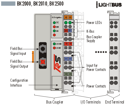
The BK2000 and BK2010 bus couplers connect the TRS-Lightbus system to the electronic terminal blocks, which can be expanded in modular fashion. One unit consists of one bus coupler, any number of up to 64 terminals and one end terminal. The BK2010 economy variant permits particularly economical creation of peripheral interfacing connections. Up to 64 digital input/output terminals can be connected.
The bus coupler recognises the connected terminals and automatically generates the affiliations of the inputs/outputs to the bytes of the process image. The first input/output signal is inserted in the first bit of one byte (LSB), beginning from the left. The bus coupler inserts further signals in this byte. Inputs and output are clearly separated. The bus coupler automatically begins a further byte if the number of inputs or outputs exceeds 8 bits.
The TRS-Lightbus System is a rapid and safe serial field bus system. The TRS-Lightbus has a ring structure, and up to 254 stations can be operated
in a ring. Easy-to-operate standard fiber-optic technology is used for data
transmission, which represents excellent value. Thanks to an optimised,
efficient telegram structure, the Lightbus achieves a very high user data
transmission rate. For the exchange of 32 bit user information 25 m s transmission time is required.
|
Order number |
Description |
|
BK2000 |
TRS Lightbus coupler for up to 64 bus terminals |
|
BK2010 |
TRS Lightbus coupler for up to 64 digital bus terminals |
|
BK2500 |
TRS Lightbus coupler with RS485 port instead of fiber optic interface |
|
KL9010 |
End terminal |
|
KS2000 |
Connecting cable, configuration software on CD for Windows 95/NT |
Complex signal processing for
analog I/Os, position measurement
The BK2000 bus coupler supports
the operation of all bus terminals. As far as the user is concerned, handling of
the analog inputs/outputs is no different to other series. The information is
available in the process image of the controller for processing in the form of
an byte-array.
The analog and multifunctional bus terminals can be adapted to each specific application using the KS2000 configuration set. Depending on the type, the analog bus terminals' registers contain temperature ranges, gain values and linearisation characteristics. Using the KS2000 software, the required parameters can be set on a PC. The bus terminal stores settings permanently and in a fail safe manner.
Optionally, the bus terminals can also be controlled by the control system. Via function blocks (FBs), the Programmable Logic Controller (PLC) or the Industrial Personal Computer (IPC) handles configuration of the complete periphery during the start up phase. If required, the controller can upload the decentrally created configuration data in order to centrally manage and store this data. Therefore, new adjustments are not necessary in the event of replacement of a bus terminal. The controller automatically sets the required setting on power up.
Thanks to the high-speed access method employed by the TRS Lightbus, it is possible to access specific peripheral data and to read or write the required data only. Data is exchanged with the required priorities without producing any overhead.
|
System data |
TRS-Lightbus (BK2000, BK2010) |
|
Number of I/O modules |
254 |
|
Number of I/O points |
16192 |
|
Data transfer medium |
Fiber optic conductor: APF (plastic)- fiber (1000 µm) or PCS- fiber (200 µm) |
|
Length between modules |
45 m APF- fiber, 600 m PCS- fiber |
|
Data transfer rate |
2.5 Mbaud |
|
Data transfer time |
0.26 ms in the case of 10 modules with 32-bit inputs and outputs each |
|
Technical data |
BK2000 | BK2010 |
|
Number of bus terminals |
64 | |
|
Digital peripheral signals |
256 inputs/outputs | 256 inputs/outputs |
|
Analog peripheral signals |
128 inputs/outputs | --- |
|
Configuration possibility |
by KS2000 or the controller | |
|
Maximum number of bytes |
512 bytes I and 512 bytes O | 32 bytes (I and O) |
|
Bus connection |
2 x standard fiber optic connector Z1000 (plastic- fiber), Z1010 (PCS fiber) | |
|
Power supply |
24 V DC (20...29 V DC) | |
|
Input current |
70 mA + (total K-Bus current)/4 | |
| 500 mA max. | 200 mA max. | |
|
Starting current |
2.5 x continuous current | |
|
Recommended fuse |
£ 10 A | |
|
K-Bus power supply up to |
1750 mA 500 mA | |
|
Power contact voltage |
24 V DC max. | |
|
Power contact current load |
10 A max. | |
|
Dielectric strength |
500 Vrms (Power contact / bus coupler supply voltage) | |
|
Weight approx. |
150 g | 130 g |
|
Operating temperature |
0°C ... +55°C | |
|
Storage temperature |
-25°C ... +85°C | |
|
Relative humidity |
95%, no condensation | |
|
Vibrations/shock resistance |
conforms to IEC 68-2-6 / IEC 68-2-27 | |
|
EMC resistance Burst / ESD |
conforms to EN 50082 (ESD, Burst) / EN 50081 | |
|
Installation position |
any | |
|
Type of protection |
IP20 | |
back | Fieldbus Terminals | Download | Home
Copyright © 2000 TRS Fieldbus Systems, Inc. All rights reserved.
Revised: June 28, 2000
.